Start With the Radiation Pattern
Radiation pattern shows how transmitted or received strength changes with direction.
- Broad pattern: covers more angles but distributes power more widely.
- Narrow main lobe: concentrates power toward a smaller region.
- Choose by task: fixed backhaul, a street sector, and a moving user need different coverage shapes.

How antennas reshape coverage
References for this section3
- C. A. Balanis, Antenna Theory: Analysis and Design, 4th ed., Wiley, 2016.
- R. J. Mailloux, Phased Array Antenna Handbook, 3rd ed., Artech House, 2017.
- MathWorks, Antenna Toolbox User's Guide: directivity, gain, and EIRP.
Gain and Beamwidth
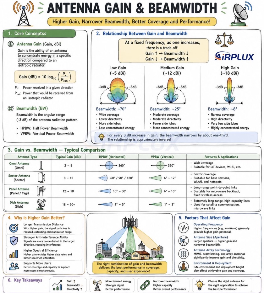
Directivity tells how concentrated the radiation is. Gain also includes power lost inside the antenna.
- : linear directivity in direction ; is dBi.
- : radiation intensity in W/sr; : total radiated power in W.
- : radiated power divided by accepted feed power; : linear directional gain.
- Physical meaning: directivity describes shape; efficiency turns it into useful gain. Neither creates power.
HPBW is the angle between the two main-lobe directions at half the peak power ( dB).
-
Horizontal cut: how broadly the sector covers a street or area.
-
Vertical cut: how much energy reaches ground users rather than sky or distant sites.
-
Caution: one cut is not the full 3D radiation pattern.
-
Narrower beam: often raises peak gain at a fixed frequency and comparable efficiency.
-
Larger electrical aperture: can help make a narrower beam.
-
Not a fixed conversion: sidelobes, 3D shape, and efficiency prevent a universal gain-to-beamwidth rule.
EIRP combines transmit power, feed loss, and directional antenna gain at a stated reference:
- : transmit power before the stated feed loss.
- : feeder/connector loss between that point and the antenna input.
- : gain toward the intended receiver, not necessarily peak gain.
- : equivalent isotropic radiated power in that direction.
- Example: 30 dBm transmit power, 2 dB feed loss, and 12 dBi gain give 40 dBm EIRP toward the beam. Poor pointing or polarization can still weaken the user link.
For port matching, return loss, isolation, radiation efficiency, and realized gain, continue with the S-parameter and antenna-metrics guide.
References for this section3
- C. A. Balanis, Antenna Theory: Analysis and Design, 4th ed., Wiley, 2016.
- R. J. Mailloux, Phased Array Antenna Handbook, 3rd ed., Artech House, 2017.
- MathWorks, Antenna Toolbox User's Guide: directivity, gain, and EIRP.
Polarization: Which Way the Electric Field Points
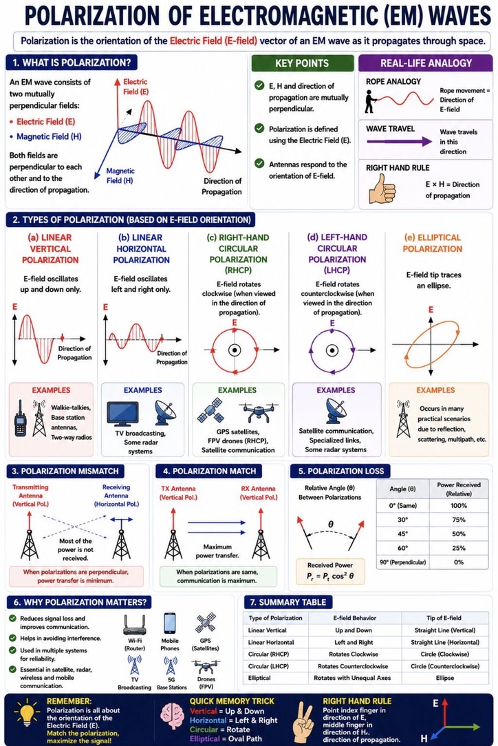
Polarization describes the path traced by the electric-field vector as the wave travels.
- Linear: the field oscillates along one fixed axis, such as vertical or horizontal.
- Circular: the field rotates with nearly constant magnitude.
- Elliptical: the field traces an ellipse; circular is its special case.
For ideal linear transmit and receive polarizations:
- : fraction of power coupled because of polarization alignment alone.
- : angle between the transmit and receive polarization axes.
- Example: gives ideal full coupling, gives half power, and gives zero in this ideal model. Real reflected paths can mix polarization.
- Dual-polarized panel: places two polarization ports in a compact antenna.
- MIMO use: ports may help separate streams, but channel independence and port isolation still decide the gain.
Polarization: transmitted and received waves
References for this section3
- C. A. Balanis, Antenna Theory: Analysis and Design, 4th ed., Wiley, 2016.
- R. J. Mailloux, Phased Array Antenna Handbook, 3rd ed., Artech House, 2017.
- MathWorks, Antenna Toolbox User's Guide: directivity, gain, and EIRP.
How Cellular Antennas Evolved
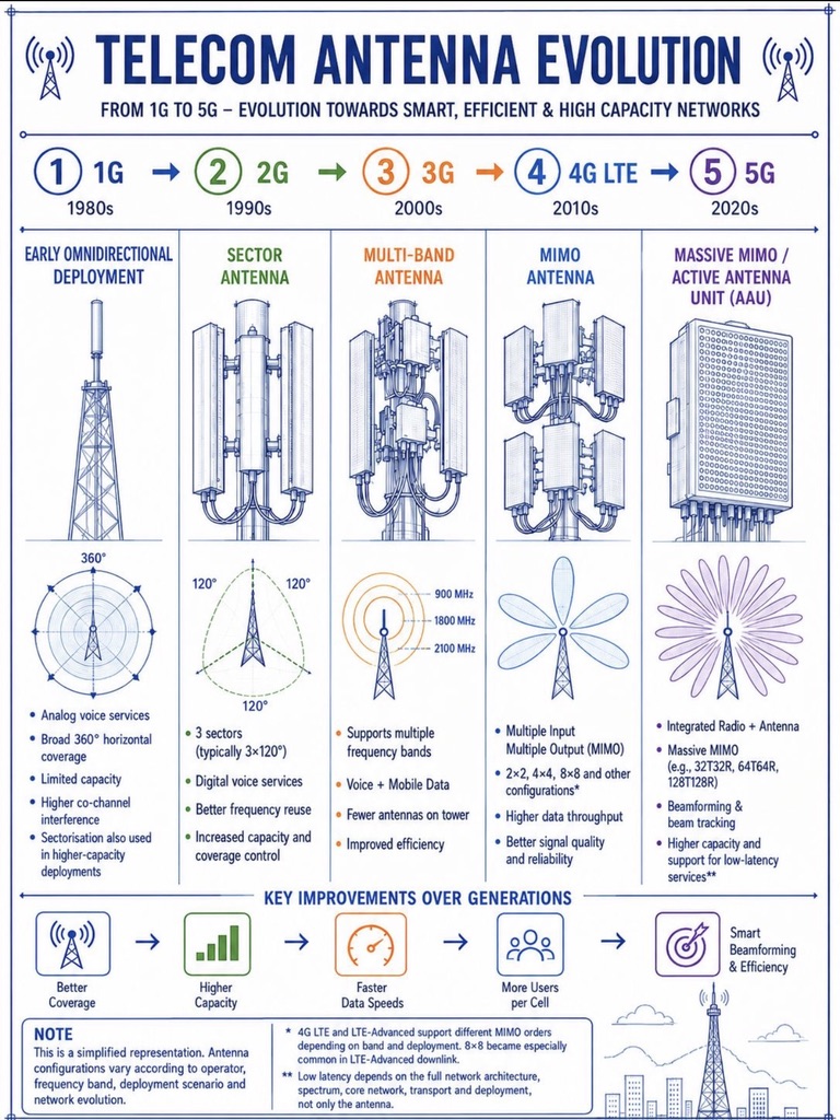
Cellular antenna design changed as networks needed more coverage control, spectrum reuse, and capacity. The timeline below is a teaching guide, not a rule that each mobile generation uses exactly one antenna type.
| Typical progression | Antenna idea | What it enabled |
|---|---|---|
| Early cellular deployments | Broad or omnidirectional coverage | Serve users over a large surrounding area |
| Sectorized sites | Directional panel antennas | Split a cell into sectors and reuse spectrum more effectively |
| Multiband sites | Several bands from one site | Support new services and spectrum without a separate tower for every band |
| MIMO deployments | Multiple antenna ports | Improve reliability or carry several spatial streams when the channel allows |
| Active arrays and massive MIMO | Many calibrated elements with electronic weights | Steer beams, schedule users spatially, and adapt coverage more precisely |
References for this section3
- C. A. Balanis, Antenna Theory: Analysis and Design, 4th ed., Wiley, 2016.
- R. J. Mailloux, Phased Array Antenna Handbook, 3rd ed., Artech House, 2017.
- MathWorks, Antenna Toolbox User's Guide: directivity, gain, and EIRP.
Connect the Ideas
Follow the physical chain:
- Coverage region: decide who must be served.
- Gain and beamwidth: decide where power goes.
- Polarization: decide how well the receiving antenna couples to it.
- Array control: use geometry, phased arrays, and MIMO to steer, focus, or separate signals.
References for this section3
- C. A. Balanis, Antenna Theory: Analysis and Design, 4th ed., Wiley, 2016.
- R. J. Mailloux, Phased Array Antenna Handbook, 3rd ed., Artech House, 2017.
- MathWorks, Antenna Toolbox User's Guide: directivity, gain, and EIRP.
Takeaway
- Narrow beam: more directional gain potential, more pointing/tracking demand.
- Polarization mismatch: can weaken a well-aimed link.
- Active array: adds control over pattern shape, without changing energy conservation.
References for this section3
- C. A. Balanis, Antenna Theory: Analysis and Design, 4th ed., Wiley, 2016.
- R. J. Mailloux, Phased Array Antenna Handbook, 3rd ed., Artech House, 2017.
- MathWorks, Antenna Toolbox User's Guide: directivity, gain, and EIRP.
Complete references and further reading
- C. A. Balanis, Antenna Theory: Analysis and Design, 4th ed., Wiley, 2016.
- R. J. Mailloux, Phased Array Antenna Handbook, 3rd ed., Artech House, 2017.
- MathWorks, Antenna Toolbox User's Guide: directivity, gain, and EIRP.