Steering and Scanning Are Related but Different
Beam steering applies a spatial weight pattern that points an array response toward a selected direction or focal point. Beam scanning tests a sequence of steering patterns to discover a user, target, path, or best communication beam.
Mechanical antennas scan by physically rotating. Phased arrays and RIS panels scan electronically by changing element phases, allowing much faster switching with no moving structure.
References for this section3
- S. Kutty and D. Sen, "Beamforming for Millimeter Wave Communications: An Inclusive Survey", IEEE Communications Surveys & Tutorials, vol. 18, no. 2, pp. 949–973, 2016.
- R. W. Heath Jr. et al., "An Overview of Signal Processing Techniques for Millimeter Wave MIMO Systems", IEEE Journal of Selected Topics in Signal Processing, vol. 10, no. 3, pp. 436–453, 2016.
- H. L. Van Trees, Optimum Array Processing, Wiley, 2002.
The Array Factor
For a uniform linear array with elements, equal amplitudes, element spacing , and progressive phase , a common array-factor form is
To steer toward , choose
At , the geometric phase and applied phase cancel, so the element contributions add coherently.
References for this section3
- S. Kutty and D. Sen, "Beamforming for Millimeter Wave Communications: An Inclusive Survey", IEEE Communications Surveys & Tutorials, vol. 18, no. 2, pp. 949–973, 2016.
- R. W. Heath Jr. et al., "An Overview of Signal Processing Techniques for Millimeter Wave MIMO Systems", IEEE Journal of Selected Topics in Signal Processing, vol. 10, no. 3, pp. 436–453, 2016.
- H. L. Van Trees, Optimum Array Processing, Wiley, 2002.
What a Radiation Pattern Contains
- Main lobe: the direction with the strongest response.
- Half-power beamwidth: angular width between points 3 dB below the main-lobe peak.
- Sidelobes: secondary maxima outside the main lobe.
- Nulls: directions with very low response.
- Grating lobes: unwanted strong replicas caused by spatial undersampling, often from excessive element spacing.
A larger electrical aperture produces a narrower main beam, giving better angular resolution. Narrow beams also make initial access and tracking harder because more candidate directions may need to be searched.
References for this section3
- S. Kutty and D. Sen, "Beamforming for Millimeter Wave Communications: An Inclusive Survey", IEEE Communications Surveys & Tutorials, vol. 18, no. 2, pp. 949–973, 2016.
- R. W. Heath Jr. et al., "An Overview of Signal Processing Techniques for Millimeter Wave MIMO Systems", IEEE Journal of Selected Topics in Signal Processing, vol. 10, no. 3, pp. 436–453, 2016.
- H. L. Van Trees, Optimum Array Processing, Wiley, 2002.
Beam Codebooks
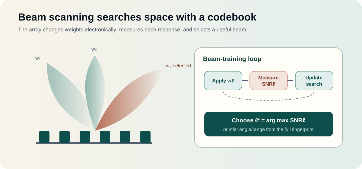
Practical systems often store a finite set of beamforming vectors called a codebook. Each vector corresponds to a direction or region.
During beam training, the transmitter and receiver test selected pairs and record a metric such as received power, SNR, SINR, or channel quality. The best measured pair is chosen for data transmission.
Codebook beams may be generated from discrete Fourier transform vectors, optimized for a specific element pattern, or learned from measurements. RIS codebooks similarly contain phase configurations rather than active transmit weights.
References for this section3
- S. Kutty and D. Sen, "Beamforming for Millimeter Wave Communications: An Inclusive Survey", IEEE Communications Surveys & Tutorials, vol. 18, no. 2, pp. 949–973, 2016.
- R. W. Heath Jr. et al., "An Overview of Signal Processing Techniques for Millimeter Wave MIMO Systems", IEEE Journal of Selected Topics in Signal Processing, vol. 10, no. 3, pp. 436–453, 2016.
- H. L. Van Trees, Optimum Array Processing, Wiley, 2002.
Scanning Strategies
References for this section3
- S. Kutty and D. Sen, "Beamforming for Millimeter Wave Communications: An Inclusive Survey", IEEE Communications Surveys & Tutorials, vol. 18, no. 2, pp. 949–973, 2016.
- R. W. Heath Jr. et al., "An Overview of Signal Processing Techniques for Millimeter Wave MIMO Systems", IEEE Journal of Selected Topics in Signal Processing, vol. 10, no. 3, pp. 436–453, 2016.
- H. L. Van Trees, Optimum Array Processing, Wiley, 2002.
Exhaustive Search
Test every candidate beam and select the best. This is robust and simple but creates high overhead when the codebook is large.
References for this section3
- S. Kutty and D. Sen, "Beamforming for Millimeter Wave Communications: An Inclusive Survey", IEEE Communications Surveys & Tutorials, vol. 18, no. 2, pp. 949–973, 2016.
- R. W. Heath Jr. et al., "An Overview of Signal Processing Techniques for Millimeter Wave MIMO Systems", IEEE Journal of Selected Topics in Signal Processing, vol. 10, no. 3, pp. 436–453, 2016.
- H. L. Van Trees, Optimum Array Processing, Wiley, 2002.
Hierarchical Search
Start with wide beams to identify a sector, then use narrower beams inside that sector. This reduces measurements but can fail if an early coarse decision is wrong.
References for this section3
- S. Kutty and D. Sen, "Beamforming for Millimeter Wave Communications: An Inclusive Survey", IEEE Communications Surveys & Tutorials, vol. 18, no. 2, pp. 949–973, 2016.
- R. W. Heath Jr. et al., "An Overview of Signal Processing Techniques for Millimeter Wave MIMO Systems", IEEE Journal of Selected Topics in Signal Processing, vol. 10, no. 3, pp. 436–453, 2016.
- H. L. Van Trees, Optimum Array Processing, Wiley, 2002.
Adaptive Search
Select the next beam using previous measurements, a channel model, Bayesian inference, or machine learning. Adaptive methods can reduce overhead but require reliable assumptions and careful handling of uncertainty.
References for this section3
- S. Kutty and D. Sen, "Beamforming for Millimeter Wave Communications: An Inclusive Survey", IEEE Communications Surveys & Tutorials, vol. 18, no. 2, pp. 949–973, 2016.
- R. W. Heath Jr. et al., "An Overview of Signal Processing Techniques for Millimeter Wave MIMO Systems", IEEE Journal of Selected Topics in Signal Processing, vol. 10, no. 3, pp. 436–453, 2016.
- H. L. Van Trees, Optimum Array Processing, Wiley, 2002.
Side Information
Position, inertial sensors, sub-6 GHz channel estimates, camera/radar sensing, or previous beam history can restrict the search region. This is especially valuable for fast-moving users and narrow mmWave beams.
References for this section3
- S. Kutty and D. Sen, "Beamforming for Millimeter Wave Communications: An Inclusive Survey", IEEE Communications Surveys & Tutorials, vol. 18, no. 2, pp. 949–973, 2016.
- R. W. Heath Jr. et al., "An Overview of Signal Processing Techniques for Millimeter Wave MIMO Systems", IEEE Journal of Selected Topics in Signal Processing, vol. 10, no. 3, pp. 436–453, 2016.
- H. L. Van Trees, Optimum Array Processing, Wiley, 2002.
A Simple Scanning Example
Suppose a base station has a 64-beam codebook covering a 120-degree sector.
- Exhaustive scanning evaluates 64 beams.
- A two-level hierarchy might test 8 broad sectors and then 8 narrow beams in the selected sector, requiring about 16 measurements.
- A location-assisted method may test only 4–6 beams around the predicted direction.
Lower overhead leaves more time for payload data, but an incorrect shortcut can select a weak beam. Evaluation should therefore report both estimation accuracy and training cost.
References for this section3
- S. Kutty and D. Sen, "Beamforming for Millimeter Wave Communications: An Inclusive Survey", IEEE Communications Surveys & Tutorials, vol. 18, no. 2, pp. 949–973, 2016.
- R. W. Heath Jr. et al., "An Overview of Signal Processing Techniques for Millimeter Wave MIMO Systems", IEEE Journal of Selected Topics in Signal Processing, vol. 10, no. 3, pp. 436–453, 2016.
- H. L. Van Trees, Optimum Array Processing, Wiley, 2002.
Beam Sweeping for RIS
An RIS cannot normally observe the channel like a full receiver. A controller applies a sequence of phase profiles while the base station or user measures the resulting signal.
Each profile creates a spatial probing pattern. The vector of measured powers or SNR values forms a beam-domain fingerprint:
The strongest entry can provide a coarse direction estimate. A regression or classification model can use the entire fingerprint to infer angle, range, position, or blockage state. This may extract more information than simple strongest-beam selection.
In the near field, profiles can focus at different angle-range points rather than only at different directions. A scan can therefore probe a three-dimensional region.
References for this section3
- S. Kutty and D. Sen, "Beamforming for Millimeter Wave Communications: An Inclusive Survey", IEEE Communications Surveys & Tutorials, vol. 18, no. 2, pp. 949–973, 2016.
- R. W. Heath Jr. et al., "An Overview of Signal Processing Techniques for Millimeter Wave MIMO Systems", IEEE Journal of Selected Topics in Signal Processing, vol. 10, no. 3, pp. 436–453, 2016.
- H. L. Van Trees, Optimum Array Processing, Wiley, 2002.
Sidelobe and Grating-Lobe Control
Uniform amplitude weights give a relatively narrow beam but visible sidelobes. Amplitude tapers such as Taylor or Chebyshev weighting reduce sidelobes at the cost of a wider main beam and reduced peak gain.
Grating lobes are different from ordinary sidelobes. They are strong spatial aliases. They are controlled primarily through element spacing, scan range, and array geometry rather than only through amplitude tapering.
References for this section3
- S. Kutty and D. Sen, "Beamforming for Millimeter Wave Communications: An Inclusive Survey", IEEE Communications Surveys & Tutorials, vol. 18, no. 2, pp. 949–973, 2016.
- R. W. Heath Jr. et al., "An Overview of Signal Processing Techniques for Millimeter Wave MIMO Systems", IEEE Journal of Selected Topics in Signal Processing, vol. 10, no. 3, pp. 436–453, 2016.
- H. L. Van Trees, Optimum Array Processing, Wiley, 2002.
Wideband Beam Squint
With phase-shifter beamforming, the same phase profile is applied across frequency. Because electrical phase depends on frequency, subcarriers away from the design frequency point in slightly different directions. This beam squint becomes more important with large fractional bandwidth, large arrays, and wide scan angles.
Mitigation options include:
- True-time-delay networks.
- Subband-dependent digital precoding.
- Smaller analogue subarrays.
- Frequency-aware codebooks.
- Joint optimization of RF and baseband weights.
References for this section3
- S. Kutty and D. Sen, "Beamforming for Millimeter Wave Communications: An Inclusive Survey", IEEE Communications Surveys & Tutorials, vol. 18, no. 2, pp. 949–973, 2016.
- R. W. Heath Jr. et al., "An Overview of Signal Processing Techniques for Millimeter Wave MIMO Systems", IEEE Journal of Selected Topics in Signal Processing, vol. 10, no. 3, pp. 436–453, 2016.
- H. L. Van Trees, Optimum Array Processing, Wiley, 2002.
Calibration and Measurement
Beam patterns depend on the complete array, not only ideal weights. Practical scanning should account for:
- Element-position and orientation errors.
- RF cable and phase-shifter mismatch.
- Mutual coupling.
- Mounting structures and radomes.
- RIS phase-amplitude coupling.
- User blockage and environmental reflections.
Over-the-air calibration measures the realized pattern or channel response. This is essential when a beam codebook designed in simulation is transferred to a physical prototype.
References for this section3
- S. Kutty and D. Sen, "Beamforming for Millimeter Wave Communications: An Inclusive Survey", IEEE Communications Surveys & Tutorials, vol. 18, no. 2, pp. 949–973, 2016.
- R. W. Heath Jr. et al., "An Overview of Signal Processing Techniques for Millimeter Wave MIMO Systems", IEEE Journal of Selected Topics in Signal Processing, vol. 10, no. 3, pp. 436–453, 2016.
- H. L. Van Trees, Optimum Array Processing, Wiley, 2002.
Applications
- Initial access and beam management in 5G/6G.
- Multi-user beam scheduling.
- Radar search and target tracking.
- Satellite and airborne links.
- Wi-Fi beamforming.
- Direction finding and localization.
- RIS-assisted coverage and sensing.
- Electronic warfare and remote sensing.
References for this section3
- S. Kutty and D. Sen, "Beamforming for Millimeter Wave Communications: An Inclusive Survey", IEEE Communications Surveys & Tutorials, vol. 18, no. 2, pp. 949–973, 2016.
- R. W. Heath Jr. et al., "An Overview of Signal Processing Techniques for Millimeter Wave MIMO Systems", IEEE Journal of Selected Topics in Signal Processing, vol. 10, no. 3, pp. 436–453, 2016.
- H. L. Van Trees, Optimum Array Processing, Wiley, 2002.
Takeaway
Beam steering chooses a spatial response; beam scanning searches across responses. Good scanning design balances angular or spatial accuracy against measurement overhead. Array aperture, element spacing, codebook design, bandwidth, calibration, mobility, and hardware resolution determine whether an elegant steering equation becomes a reliable real-world beam.
References for this section3
- S. Kutty and D. Sen, "Beamforming for Millimeter Wave Communications: An Inclusive Survey", IEEE Communications Surveys & Tutorials, vol. 18, no. 2, pp. 949–973, 2016.
- R. W. Heath Jr. et al., "An Overview of Signal Processing Techniques for Millimeter Wave MIMO Systems", IEEE Journal of Selected Topics in Signal Processing, vol. 10, no. 3, pp. 436–453, 2016.
- H. L. Van Trees, Optimum Array Processing, Wiley, 2002.
Complete references and further reading
- S. Kutty and D. Sen, "Beamforming for Millimeter Wave Communications: An Inclusive Survey", IEEE Communications Surveys & Tutorials, vol. 18, no. 2, pp. 949–973, 2016.
- R. W. Heath Jr. et al., "An Overview of Signal Processing Techniques for Millimeter Wave MIMO Systems", IEEE Journal of Selected Topics in Signal Processing, vol. 10, no. 3, pp. 436–453, 2016.
- H. L. Van Trees, Optimum Array Processing, Wiley, 2002.