Phase as a Spatial Control Variable
A sinusoidal signal repeats every 360 degrees, or radians. Two waves with the same frequency can arrive with different phases because they travelled different distances or were intentionally delayed.
- Waves aligned in phase add constructively.
- Waves separated by approximately 180 degrees add destructively when their amplitudes are equal.
An antenna array exploits this principle. Each element transmits a related waveform with a controlled phase. The waves combine differently in different directions, creating a strong main beam, weaker sidelobes, and sometimes deliberate nulls.
References for this section3
- H. L. Van Trees, Optimum Array Processing, Wiley, 2002.
- S. Kutty and D. Sen, "Beamforming for Millimeter Wave Communications: An Inclusive Survey", IEEE Communications Surveys & Tutorials, vol. 18, no. 2, pp. 949–973, 2016.
- E. Basar et al., "Wireless Communications Through Reconfigurable Intelligent Surfaces", IEEE Access, vol. 7, pp. 116753–116773, 2019.
Phase Shift and Time Delay
For a single-frequency signal, a time delay produces phase shift
Equivalently, an extra propagation distance produces
The negative sign indicates that a delayed wave lags in phase. Sign conventions vary across textbooks and software, so consistency is more important than memorizing one sign.
References for this section3
- H. L. Van Trees, Optimum Array Processing, Wiley, 2002.
- S. Kutty and D. Sen, "Beamforming for Millimeter Wave Communications: An Inclusive Survey", IEEE Communications Surveys & Tutorials, vol. 18, no. 2, pp. 949–973, 2016.
- E. Basar et al., "Wireless Communications Through Reconfigurable Intelligent Surfaces", IEEE Access, vol. 7, pp. 116753–116773, 2019.
Steering a Linear Array
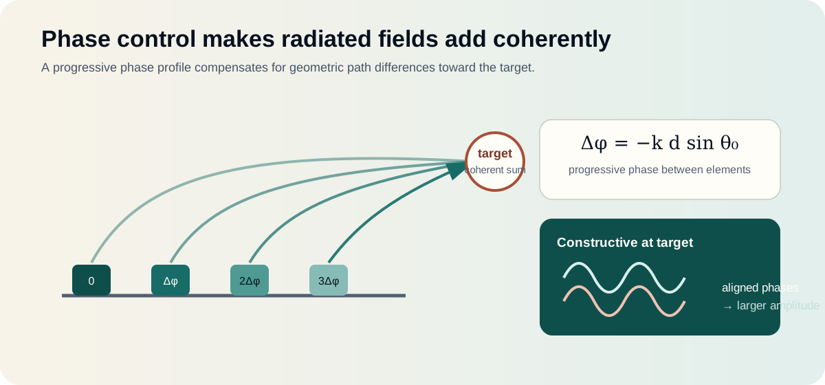
For adjacent elements separated by , steering toward angle requires a progressive phase difference with magnitude
or in degrees,
The weights across an -element array then follow a progression such as
References for this section3
- H. L. Van Trees, Optimum Array Processing, Wiley, 2002.
- S. Kutty and D. Sen, "Beamforming for Millimeter Wave Communications: An Inclusive Survey", IEEE Communications Surveys & Tutorials, vol. 18, no. 2, pp. 949–973, 2016.
- E. Basar et al., "Wireless Communications Through Reconfigurable Intelligent Surfaces", IEEE Access, vol. 7, pp. 116753–116773, 2019.
Worked Example at 28 GHz
At , the free-space wavelength is
For and ,
Adjacent elements therefore need an approximately 84-degree phase progression under this angle convention. The actual programmed sequence may use or depending on array orientation, transmit/receive convention, and steering direction.
References for this section3
- H. L. Van Trees, Optimum Array Processing, Wiley, 2002.
- S. Kutty and D. Sen, "Beamforming for Millimeter Wave Communications: An Inclusive Survey", IEEE Communications Surveys & Tutorials, vol. 18, no. 2, pp. 949–973, 2016.
- E. Basar et al., "Wireless Communications Through Reconfigurable Intelligent Surfaces", IEEE Access, vol. 7, pp. 116753–116773, 2019.
Beamforming Weights
A general complex beamforming weight is
where controls amplitude and controls phase. Phase-only beamforming keeps amplitude approximately constant and adjusts only phase. This is efficient for analogue arrays and RIS hardware, but it offers less freedom than fully complex digital weights.
References for this section3
- H. L. Van Trees, Optimum Array Processing, Wiley, 2002.
- S. Kutty and D. Sen, "Beamforming for Millimeter Wave Communications: An Inclusive Survey", IEEE Communications Surveys & Tutorials, vol. 18, no. 2, pp. 949–973, 2016.
- E. Basar et al., "Wireless Communications Through Reconfigurable Intelligent Surfaces", IEEE Access, vol. 7, pp. 116753–116773, 2019.
Maximum-Ratio Beamforming
Maximum-ratio transmission aligns the transmitted signal with the conjugate of the desired channel. The contributions then add coherently at the intended receiver. This maximizes received SNR for a single user under a transmit-power constraint, but it does not necessarily suppress interference toward other users.
References for this section3
- H. L. Van Trees, Optimum Array Processing, Wiley, 2002.
- S. Kutty and D. Sen, "Beamforming for Millimeter Wave Communications: An Inclusive Survey", IEEE Communications Surveys & Tutorials, vol. 18, no. 2, pp. 949–973, 2016.
- E. Basar et al., "Wireless Communications Through Reconfigurable Intelligent Surfaces", IEEE Access, vol. 7, pp. 116753–116773, 2019.
Zero-Forcing Beamforming
Zero forcing chooses weights that create nulls in specified channel directions. It can strongly reduce multi-user interference when the channel matrix has enough independent dimensions. Its cost is sensitivity to channel errors and potential noise or power amplification when user channels are nearly parallel.
References for this section3
- H. L. Van Trees, Optimum Array Processing, Wiley, 2002.
- S. Kutty and D. Sen, "Beamforming for Millimeter Wave Communications: An Inclusive Survey", IEEE Communications Surveys & Tutorials, vol. 18, no. 2, pp. 949–973, 2016.
- E. Basar et al., "Wireless Communications Through Reconfigurable Intelligent Surfaces", IEEE Access, vol. 7, pp. 116753–116773, 2019.
MMSE Beamforming
Minimum mean-square error processing balances desired gain, interference suppression, and noise. It often behaves like MRT at low SNR and approaches ZF when interference dominates and channel estimates are reliable.
References for this section3
- H. L. Van Trees, Optimum Array Processing, Wiley, 2002.
- S. Kutty and D. Sen, "Beamforming for Millimeter Wave Communications: An Inclusive Survey", IEEE Communications Surveys & Tutorials, vol. 18, no. 2, pp. 949–973, 2016.
- E. Basar et al., "Wireless Communications Through Reconfigurable Intelligent Surfaces", IEEE Access, vol. 7, pp. 116753–116773, 2019.
Phase Quantization
Real hardware rarely produces any continuous phase value perfectly. A -bit phase shifter provides nominal states.
| Resolution | States | Ideal spacing |
|---|---|---|
| 1 bit | 2 | 180° |
| 2 bit | 4 | 90° |
| 3 bit | 8 | 45° |
| 6 bit | 64 | 5.625° |
For the 84-degree example, a 6-bit phase shifter would select the nearest available step, around 84.375 degrees. A 1-bit device must approximate the desired profile much more coarsely, which increases quantization lobes and reduces ideal coherent gain.
RIS prototypes often use low-bit control because it reduces switch count, biasing complexity, cost, and control overhead. The system designer trades electromagnetic accuracy for practical implementation.
References for this section3
- H. L. Van Trees, Optimum Array Processing, Wiley, 2002.
- S. Kutty and D. Sen, "Beamforming for Millimeter Wave Communications: An Inclusive Survey", IEEE Communications Surveys & Tutorials, vol. 18, no. 2, pp. 949–973, 2016.
- E. Basar et al., "Wireless Communications Through Reconfigurable Intelligent Surfaces", IEEE Access, vol. 7, pp. 116753–116773, 2019.
Phase Errors and Real Hardware
The commanded phase is not always the realized phase. Important impairments include:
- Phase-dependent insertion or reflection loss.
- Different responses across frequency.
- Manufacturing variation between elements.
- Mutual coupling.
- RF-chain gain and phase mismatch.
- Temperature and bias-voltage drift.
- Angle-dependent unit-cell response.
Calibration measures these errors and adjusts the control values. Without calibration, a mathematically correct beamformer can point in the wrong direction or lose coherent gain.
References for this section3
- H. L. Van Trees, Optimum Array Processing, Wiley, 2002.
- S. Kutty and D. Sen, "Beamforming for Millimeter Wave Communications: An Inclusive Survey", IEEE Communications Surveys & Tutorials, vol. 18, no. 2, pp. 949–973, 2016.
- E. Basar et al., "Wireless Communications Through Reconfigurable Intelligent Surfaces", IEEE Access, vol. 7, pp. 116753–116773, 2019.
Narrowband Phase Shift vs True Time Delay
A fixed phase shift corresponds to the correct time delay at only one frequency. In a wideband array, different frequencies can point toward different angles—a phenomenon called beam squint.
True-time-delay hardware applies an actual delay rather than a frequency-independent phase. It provides more consistent steering across a wide bandwidth but is typically more complex and costly.
References for this section3
- H. L. Van Trees, Optimum Array Processing, Wiley, 2002.
- S. Kutty and D. Sen, "Beamforming for Millimeter Wave Communications: An Inclusive Survey", IEEE Communications Surveys & Tutorials, vol. 18, no. 2, pp. 949–973, 2016.
- E. Basar et al., "Wireless Communications Through Reconfigurable Intelligent Surfaces", IEEE Access, vol. 7, pp. 116753–116773, 2019.
SNR Gain and Conservation of Energy
Beamforming does not create energy. It redistributes radiation spatially. Increasing gain toward one direction changes the pattern elsewhere. For an ideal coherent -element array, field amplitudes can add proportionally to in the target direction, while total radiated power and normalization determine the final array-gain interpretation.
Care is therefore needed when comparing simulations. A fair comparison must state whether total transmit power or per-element power is held constant.
References for this section3
- H. L. Van Trees, Optimum Array Processing, Wiley, 2002.
- S. Kutty and D. Sen, "Beamforming for Millimeter Wave Communications: An Inclusive Survey", IEEE Communications Surveys & Tutorials, vol. 18, no. 2, pp. 949–973, 2016.
- E. Basar et al., "Wireless Communications Through Reconfigurable Intelligent Surfaces", IEEE Access, vol. 7, pp. 116753–116773, 2019.
Takeaway
Phase control compensates for geometric path differences. When phases are aligned, useful signals add; when weights are designed to oppose an unwanted channel, interference can be reduced. Practical beamforming performance depends on phase resolution, bandwidth, CSI accuracy, calibration, element response, and power normalization.
References for this section3
- H. L. Van Trees, Optimum Array Processing, Wiley, 2002.
- S. Kutty and D. Sen, "Beamforming for Millimeter Wave Communications: An Inclusive Survey", IEEE Communications Surveys & Tutorials, vol. 18, no. 2, pp. 949–973, 2016.
- E. Basar et al., "Wireless Communications Through Reconfigurable Intelligent Surfaces", IEEE Access, vol. 7, pp. 116753–116773, 2019.
Complete references and further reading
- H. L. Van Trees, Optimum Array Processing, Wiley, 2002.
- S. Kutty and D. Sen, "Beamforming for Millimeter Wave Communications: An Inclusive Survey", IEEE Communications Surveys & Tutorials, vol. 18, no. 2, pp. 949–973, 2016.
- E. Basar et al., "Wireless Communications Through Reconfigurable Intelligent Surfaces", IEEE Access, vol. 7, pp. 116753–116773, 2019.